
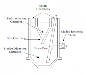
This article introduces the code requirements for the septic systems.
The following code requirements provided after the thorough research to protect every family’s health and to safeguard the property value and mainly to keep hygiene surroundings. The code requirements will cover the present and the future wants of an individual.
Say for an example, if you decided to construct the small home and to enlarge it in future as the family grows, it is more important to design the septic system in larger size according to the family size and needs. If you planned to modify an existing home, it is to be noted in mind that the alterations can affect the disposal method of wastewater.
In addition to this, the garbage disposal, occupants and other wastage can raise the waste water volume. It is must to be aware of the septic system located in your home, so you will not damage it constructing the detached building, paved areas around the septic system area or absorption area. You can call a septic tank service in flowery branch if you are located there.
Local Regulations for Septic Tanks
At the time of septic system installation process, people should consult their Local Code Enforcement manager and County Health Department before they install, where the rules and regulations set by the County Health Department officers.
Permit Requirements for Septic Tanks
Upon request, the permit for the septic system installation should required a certain permit from the Community Health Department on any new or existing on-site garbage disposal system. On the construction of new building, it is essential to obtain particular permit from the concerned department and building officials for the septic system installation before they construct the building.
Inspection for Septic Tanks
The septic system installer demonstrate an awareness of the local environmental health code and make the payment of annual fees to Community Health Department which is located in every local country environment health office. The septic system installer who installs it for their own residence is required to receive permit for septic system installation at least with minimum standards. The final approval and inspection should be obtained on or before earth cover. The Community Health Department and Environment Health Office will be notified to the concerned person who installs septic system at least 24 hours prior to the inspection time.
Septic System Requirements
Here provided the code requirements of septic system. They are as follows,
Sewer Lines – to pressure water line from 10 feet.
Dry Wells Water Table – with minimum of 4 ft for the absorption area with narrow ground.
Septic System Tanks – should be water tight for inlet and outlet pipelines.
Outlets – to cover the outlet end of the septic systems.
Pumps and Alternating Devices – to access ground surface with lid and riser.
Final Cover – to avoid the surface drainage water and it should not exceed 3 feet.
Holding Tanks – for the construction of an existing home.
Sprinkler Systems – while installing the septic system, it is important to research the condition of the soil type to treat the effluent from the tank. To test the soil, the percolation testing will be taken place to see the how much volume of water to soak into the sand to reduce and avoid the risks of water pollution under the ground.
It is important to watch the septic system code requirements so that you know the rules of your local jurisdiction.
Click here for more information.
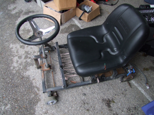
 The easiest way to control a RC motor is with a RC speed controller. Theyre cheap, powerful, and tuned to work with the relatively high-kV, low-inductance motors. Theyre also sensorless. I started off using a turnigy dLux 80A HV controller. Id heard that theyre good, reliable controllers. And the one I had sort of worked. The problem ran into was that the ESC itself was a small, mostly plastic box less than two inches in the largest dimension. And since the motor was at peak current draw most of the time, the controller got pretty hot. I tried attaching a massive server heat sink to it, which despite looking pretty comical worked fairly well. Until it blew the main power bus caps. I replaced the controller, but the new one suffered the same fate. Clearly, the dLux was just not up to the task. So I moved on up to a turnigy sentilon 100A ESC. Also sensorless, also with a reputation for being bulletproof. This one actually was. I raced the majority of the season on it, only finally killing it in the endurance final in New York. Turns out running close to 3kW through an exposed system in the rain doesnt end well.
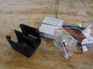 I was trying to keep too much of it the same. So I replaced everything.


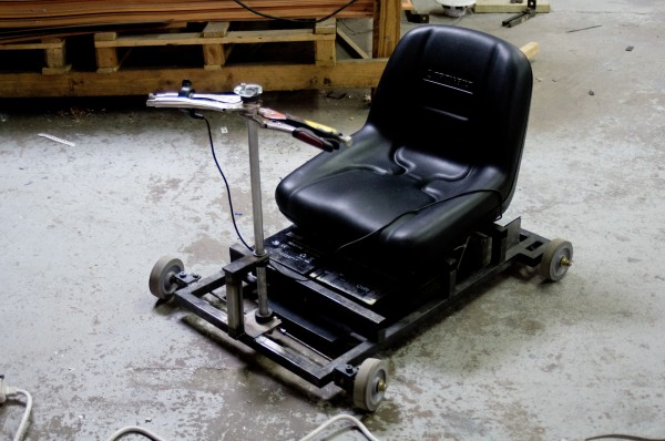
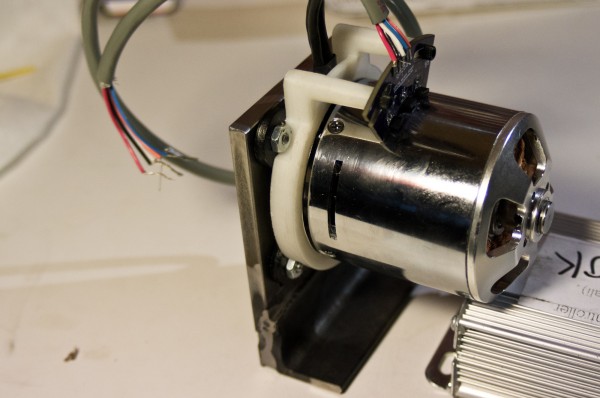
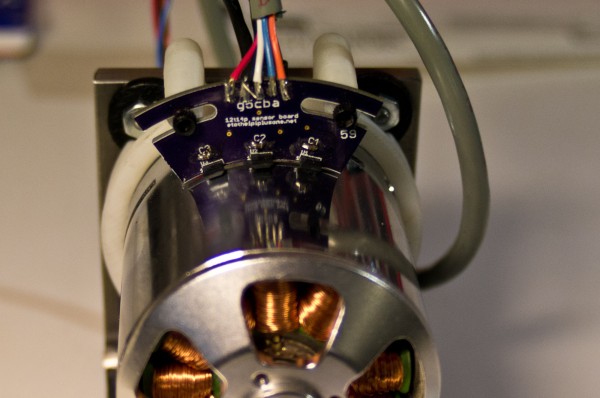
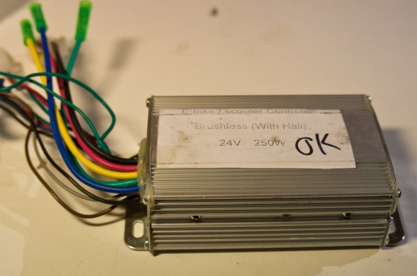
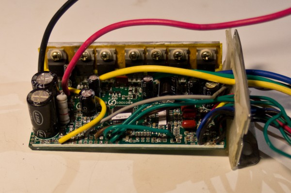
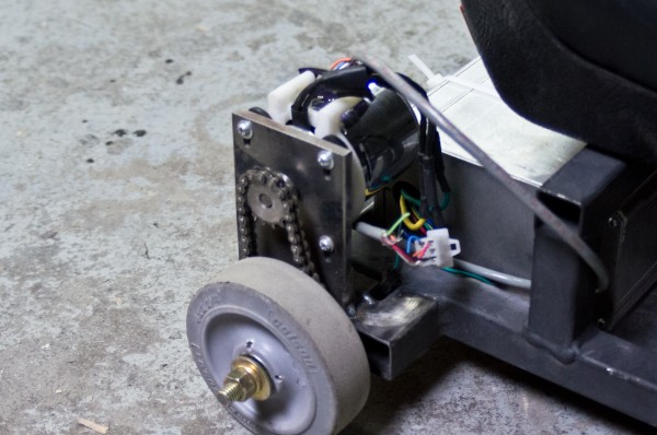
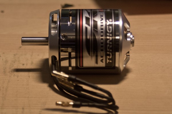
 Charles recently posted about adding sensors to sensorless motors and driving them with Jasontrollers. And I realized that it was what I wanted to do, so I emailed him. And being the awesome guy he is (and a fellow lover of tiny brushless things), he emailed back, and I ended up with some sensors to put on a motor. I pulled the motor off TinyBike, popped the sensor ring on it, whipped up a quick mounting plate, and went off in search of a Jasontroller. Fortunately, I had one lying around. Unfortunately, I had cleaned up the wiring and modded the circuit board, meaning all the stuff I needed to hook up the sensors was gone. Dang. So I ordered another Jasontroller. And now I wait.