

Before I begin, be warned. A picture is worth a thousand words, and I dont have any pictures today, so this post is going to be a pretty big wall o text. If youre willing to brave my rambles, read on.
Im currently finishing up my latest revision of ChibiTroller (v2.0), and since I first began controlling larger-scale bruushless things Ive gone through many different controllers. Most of which Ive blown up. This is a reflection and analysis of what Ive gone through so far, and what Ive learned.
My first large-scale brushless project was my Power Racing Series car last year, the bluesmobile. The power train was almost entirely made of RC plane parts, the core of which was a 2800W outrunner. There are a couple of problems with controlling a motor of that size. First of all, its just kind of massive, and so an appropriate controller is difficult to find. But a bigger problem is the commutation. Brushless motors require some kind of position feedback going to the controller in order for the controller to switch the phases to make the rotate. Usually, in the RC world the motors use sensorless commutation. Power will be flowing through any two phases at a given moment, and the controller reads the back EMF coming out of the third, unused phase in order to figure out the motors position. The problem with this is that in order to be able to get that back EMF, the motor has to be spinning at some minimum velocity. If the motor isnt under any load, it can jolt to a start from a standstill, but under load or at low speed (such as starting an electric vehicle), sensorless commutation just doesnt work. Its easy enough to get around the slow speed bit by putting a big gear reduction on the motor, but the vehicle must already be moving in order to start the motor. Thats problematic, to say the least. That being said, its often worth the inconvenience because the controllers are easy.
 The easiest way to control a RC motor is with a RC speed controller. Theyre cheap, powerful, and tuned to work with the relatively high-kV, low-inductance motors. Theyre also sensorless. I started off using a turnigy dLux 80A HV controller. Id heard that theyre good, reliable controllers. And the one I had sort of worked. The problem ran into was that the ESC itself was a small, mostly plastic box less than two inches in the largest dimension. And since the motor was at peak current draw most of the time, the controller got pretty hot. I tried attaching a massive server heat sink to it, which despite looking pretty comical worked fairly well. Until it blew the main power bus caps. I replaced the controller, but the new one suffered the same fate. Clearly, the dLux was just not up to the task. So I moved on up to a turnigy sentilon 100A ESC. Also sensorless, also with a reputation for being bulletproof. This one actually was. I raced the majority of the season on it, only finally killing it in the endurance final in New York. Turns out running close to 3kW through an exposed system in the rain doesnt end well.
So what were the successes and the failures of this particular batch of controllers? They were all cheap, and they had a high current capacity. They were fairly durable (especially the sentilon, which died of a short circuit rather than detonating), and they were able to operate the motor to its limit. But their biggest shortcoming is the commutation. The sensorless commutation is fine for spinning a propeller. And its fine for vehicles like bicycles or scooters where giving a gentle kick-start is easy. But when sitting in a small electric car, thats just plain unacceptable. Because of that controller, I blew more starts than Mark Webber, and I stalled and overheated my motors more times that I care to count. In order to do better, I need sensored commutation.
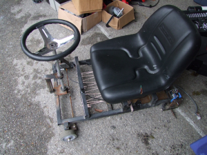
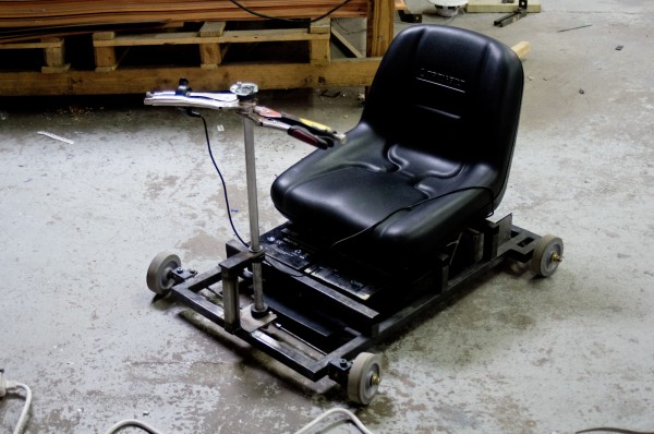
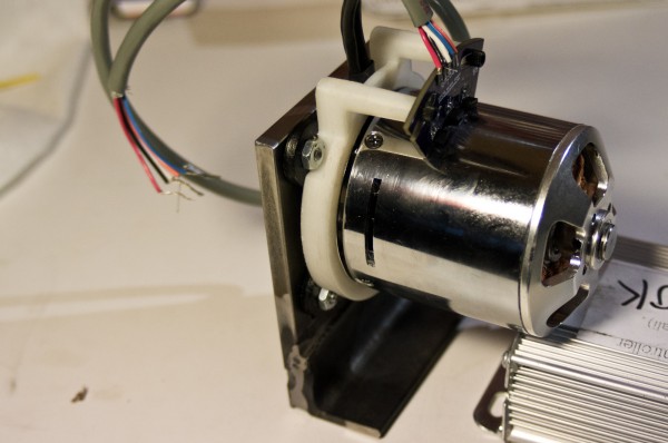
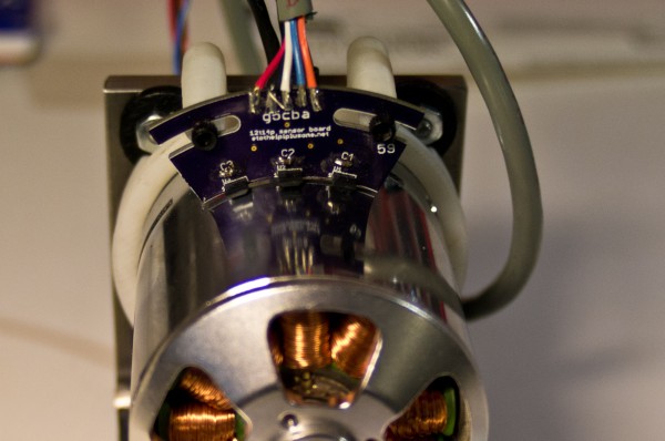
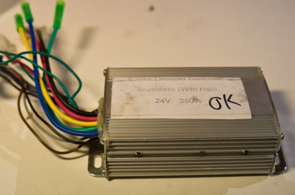
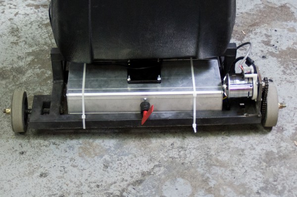
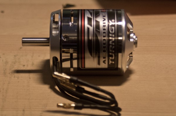
This year, I endeavored to build a chibikart of sorts. Like the original, I used a brushless motor for power. But unlike last year, I decided to learn from my mistakes and go for proper sensored control. After some discussion with Charles, I ended up with a nice set of sensors for my motors. Hall effect sensors are mounted to the motor in such a fashion so that they pick up the magnets in the can as they spin by. That way, the controller doesnt have to rely on back EMF to have position feedback, and so the motor can commutate properly at stall and low-speed conditions. The problem then is finding a controller that supports sensored commutation. This isnt difficult if you have a lot of money to throw at the problem, but really can be on a budget. Once again, Charles saved the day with the Jasontroller. These are shady no-name motor controllers from China. They support both sensored and sensorless motors, and have effective current limiting so that they dont overheat and self-destruct. Which all sounds very nice, and is very nice. I ran them successfully fir quite some time, until I decided that the 10 phase amps they could provide just wasnt enough. I found the current sensing shunt, shorted it out to lower the resistance and raise the current limit, and nothing. They had some kind of interlock in place and bricked themselves. I did all sorts of experiments on them, and ended up bricking six of them before moving on. The verdict: Jasontrollers are awesome, but not powerful or easily hackable.
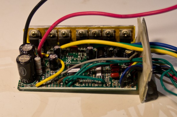
My next pick was even shadier (as anything ordered from alibaba is). They turned out to almost be Jasontrollers. They were about half the size, but had what appeared to be very similar circuitry inside. I ran a race on them, and found them to not be terribly useful for my purposes. As with all of the shady Chinese motor controllers, the mini-Jasontrollers (µtrollers) have a fairly low switching frequency, and therefore cant run the motors very fast. Because of the difference in commutation algorithms, the normal Jasontrollers would be able to go faster in sensorless mode. So once the motors were out of the conditions conditions where sensors were necessary, they would switch to sensorless. The µtrollers didnt do that, and as a result didnt go nearly as fast when using the motor sensors. During the race, I found that when in sensored mode, I would be going a good 3mph slower than in sensorless mode. Again, no good. The current output of the µtrollers is also limited to 10A, and they also bricked when I tried to up that.
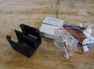
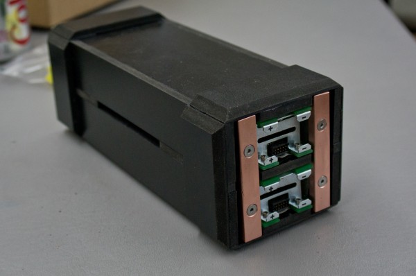
And so that brings me to the most recent (and I hope the last) chapter of my search for a good motor controller. I bit the bullet, and purchased kelly KBS24101 controllers. These arent shady. They arent cheap. But they are programmable, and they support sensors. They have higher current limits. And they shouldnt self-destruct. In a few weeks (after the race in Kansas City), Ill be able to analyze their performance. But in the mean time, all I can do is run wire and hope.
 I was trying to keep too much of it the same. So I replaced everything.


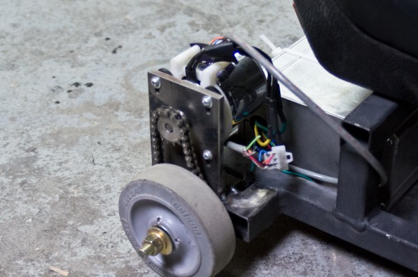
 Charles recently posted about adding sensors to sensorless motors and driving them with Jasontrollers. And I realized that it was what I wanted to do, so I emailed him. And being the awesome guy he is (and a fellow lover of tiny brushless things), he emailed back, and I ended up with some sensors to put on a motor. I pulled the motor off TinyBike, popped the sensor ring on it, whipped up a quick mounting plate, and went off in search of a Jasontroller. Fortunately, I had one lying around. Unfortunately, I had cleaned up the wiring and modded the circuit board, meaning all the stuff I needed to hook up the sensors was gone. Dang. So I ordered another Jasontroller. And now I wait.


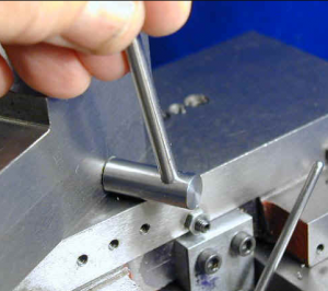 My tool post was butting up against the edge of the compound, and so I couldnt rotate it to set it straight. Actually, When I first got the tool post, it didnt fit at all. I had to mill a bit away so it would sit flat. I didnt think to mill away enough to be able to turn the post. Derp.